
Power Electronics Insights — a PA International technical series
An EV onboard charger has a quietly difficult job: take grid AC, turn it into hundreds of volts of clean DC, fit into a box small enough to tuck into a vehicle, and keep doing it for fifteen years. Most of that difficulty lands on the magnetics. The resonant transformer and its companion inductors are the largest passive components in the power path, the hardest to cool, and the ones whose parasitics — leakage inductance, inter-winding capacitance, AC winding resistance — quietly set the ceiling on what the topology can achieve.
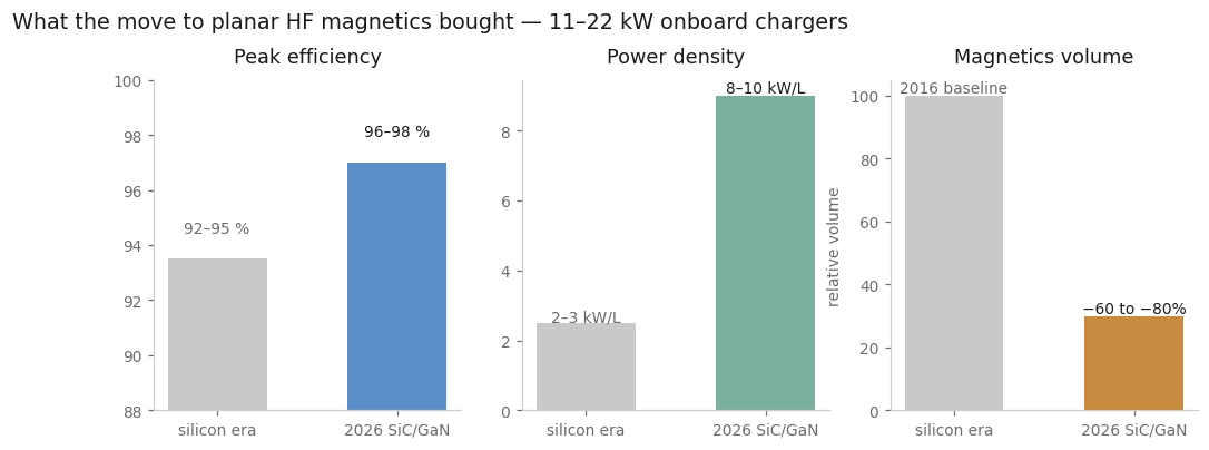
Over the past decade that problem has been comprehensively redesigned. Chargers moved from 3.3–6.6 kW unidirectional units to 11–22 kW bidirectional, V2G-ready systems; peak efficiency climbed from 92–95% to 96–98% and beyond; and power density jumped from 2–3 kW/L to 8–10 kW/L or more. The single largest contributor to that shrink was the transition from discrete wire-wound magnetics to planar, PCB-integrated transformers and inductors.
Why higher frequency shrinks the transformer
The lever behind the whole shift is switching frequency. In an LLC or CLLC resonant converter — the dominant DC-DC topology for 11–22 kW onboard chargers — the transformer must handle high-frequency AC while providing galvanic isolation and low leakage inductance, typically below 5–10 µH. Silicon-era designs switched at 50–150 kHz. SiC and GaN devices moved that to 200–500 kHz and higher.
The physics is compact. The volt-second product a core must support is V × ton = N × Ae × ΔB: applied voltage times on-time equals turns count times effective core area times flux swing. Raise the frequency and the on-time falls, so for the same power throughput the designer can shrink the core area, the turns count, or both. In practice both are traded, which is why magnetics volume in modern onboard chargers has fallen 60–80% against the 2016 baseline.
The gain is not free. Core loss follows a Steinmetz-type relation — it rises steeply with both frequency and flux swing — so higher frequency demands either lower peak flux density or better core material to stay inside the same thermal envelope. Skin depth shrinks, proximity effect between adjacent conductors intensifies, and AC winding resistance climbs. Smaller and lighter, yes — but only with far more precise winding geometry.
Planar construction: the winding becomes a PCB
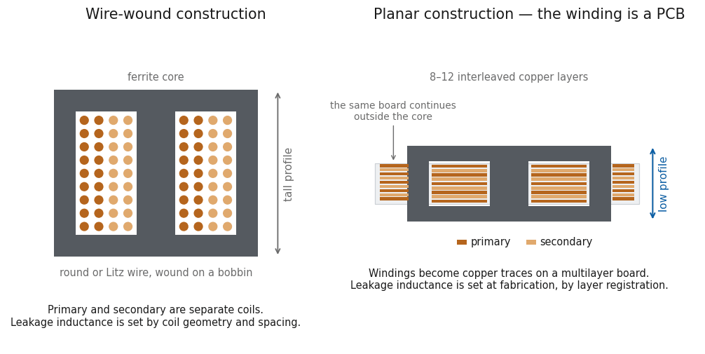
A planar transformer replaces the bobbin and round or Litz wire with copper traces on a multilayer PCB, wound around a low-profile core. For EV onboard chargers and 50–250 kW-class solar inverters alike, planar construction delivers 40–70% volume reduction, superior unit-to-unit repeatability, and a much better thermal path than wire-wound designs.
The 2026 design playbook looks like this:
Interleaved windings. Primary and secondary layers alternate through an 8–12 layer stack to minimise proximity effect and leakage inductance. The winding geometry is now a layout exercise as much as a magnetics one — interleaved multilayer PCB windings are literally fabricated as printed circuit boards.
Integrated resonant elements. The series resonant inductor in an LLC stage is often realised as the transformer’s own controlled leakage inductance, or as a separate planar winding on the same core — one discrete component eliminated, one alignment problem removed.
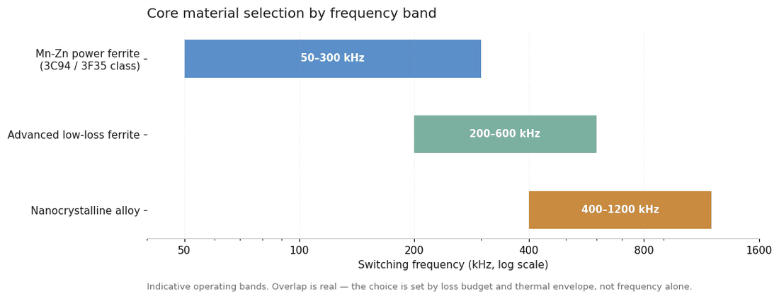
Core material by frequency band. Mn-Zn power ferrites of the 3C94/3F35 class carry designs to roughly 100–300 kHz. Beyond 400 kHz, nanocrystalline alloys and advanced low-loss ferrites take over, keeping core losses below about 50 mW/cm³ at 100 °C. Nanocrystalline material cuts losses 50–70% against traditional ferrite at these frequencies, at the cost of more demanding handling — the material is brittle, and cutting and annealing precision directly affects final core loss.
Thermal paths into the board. Arrays of thermal vias under the core and thick copper inlays — 0.5–1 mm — conduct heat straight into the metal substrate or cold plate, instead of hoping it escapes through the winding surface.
The tolerances that decide the outcome
Here is the uncomfortable truth of planar magnetics: the schematic values are decided at the fabrication stage. Achieving consistent leakage inductance and low inter-winding capacitance requires layer registration held to roughly ±20–25 µm and tight control of dielectric thickness. Over-etching of fine traces on inner layers can raise AC resistance by 15–25% — invisible on a DC resistance check, very visible in the thermal camera at full load. Automated optical inspection and X-ray are mandatory at production volume, and repeatable inductance tolerance in the region of 1%, with thermal stability to 150 °C and above, is what separates a production part from a promising prototype.
This is the part PA International supplies. Through its network of specialist manufacturing partners, PA delivers planar transformers and resonant inductors for CLLC and DAB topologies up to the 30 kW class, alongside custom inductors and PFC chokes and common-mode filters. Those partner lines run pulse-plating with AOI and X-ray inspection, hold layer registration within ±20–25 µm, and support defect rates below 50 ppm — the tolerances above are their daily production discipline, and planar transformer efficiencies above 99% at 300 kHz in 22 kW-class resonant designs are the result.
If the design sits at the boundary between low-frequency iron and high-frequency ferrite, our high-frequency and switch-mode magnetics pages set out where each construction earns its place.
Where this is heading
The next horizon is already visible: 1 MHz-plus operation on GaN, embedded cooling channels inside planar cores, and solid-state transformer architectures that use high-frequency isolation to replace 50 Hz iron entirely. PA International’s manufacturing partners are investing in exactly these capabilities — higher-frequency winding, embedded core cooling, higher-voltage partial-discharge test — which gives PA access to next-generation process capability as it matures.
If you are designing an onboard charger or DC-DC stage and the magnetics are on the critical path, that is a conversation worth having early — the winding geometry and the core material choice are much cheaper to get right before the first prototype batch than after it. Request a quote for a custom magnetic design, or tell us what the topology needs to do and we will tell you what the magnetics need to be.
Power Electronics Insights is PA International’s technical series for power-electronics engineers. Technical reference only; performance figures are aggregated from publicly available industry data (Yole Développement, IDTechEx, IEEE publications, Fraunhofer IZM) and PA International’s manufacturing-partner programme.