
Power Electronics Insights — a PA International technical series
Almost every power-conversion design eventually needs to know how much current is flowing somewhere — for protection, for control-loop feedback, for metering, or for all three. The engineer reaches for one of three well-established technologies: a current transformer, a shunt resistor, or a Hall-effect sensor. Each measures current by a genuinely different physical mechanism, and that difference doesn’t stay in the datasheet — it flows straight through into what the manufacturing partner has to build, wind, insulate and test, and into how accurately the finished quote matches the finished part.
Three technologies, three physical mechanisms
A current transformer (CT) works like any transformer: the conductor carrying the current to be measured acts as a single-turn primary, a wound secondary produces a scaled-down current, and a burden resistor turns that into a voltage. The result is galvanically isolated by construction, handles high currents without dissipating much power itself, and is the default choice wherever isolation is mandatory — but it cannot measure true DC (no changing flux, no induced signal) and its frequency response is bounded by the core.
A shunt resistor is the conceptually simplest option: a precision low-value resistor sits directly in the current path, and the voltage across it is proportional to current by Ohm’s law. Shunts measure DC and AC alike, are inexpensive, and their accuracy is limited mainly by resistor tolerance and thermal drift — but they are not isolated (the measurement sits at line potential unless paired with an isolation amplifier) and they dissipate real power as I²R loss, which becomes a genuine design constraint at high current.
A Hall-effect sensor measures the magnetic field generated by the current-carrying conductor, without breaking the circuit or adding series resistance. Closed-loop (compensated) Hall sensors trade some cost and complexity for excellent linearity and bandwidth; open-loop designs are cheaper and simpler at the cost of accuracy and temperature drift. Hall sensors measure DC through moderate AC frequencies, provide isolation inherently, and add essentially no insertion loss — but they are the most sensitive of the three to external magnetic fields and to how carefully the sensing element is positioned relative to the conductor.
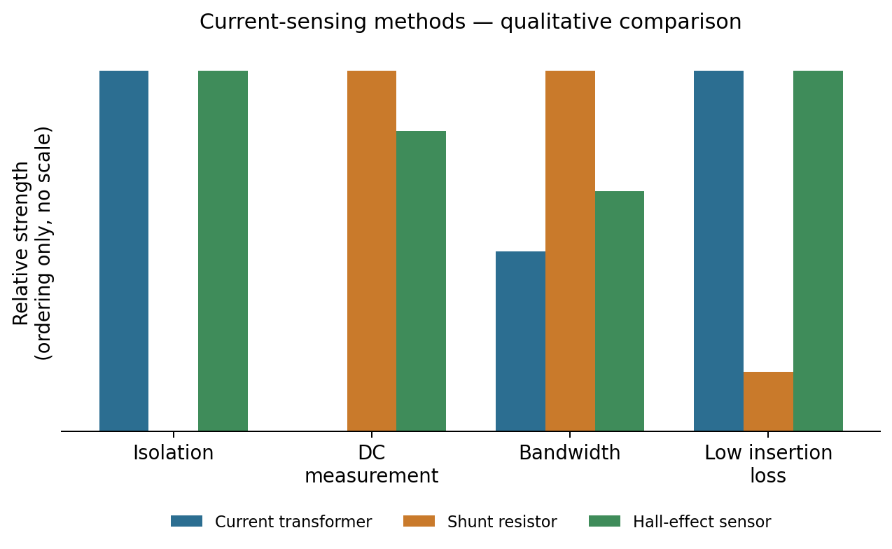
Decision table
| Criterion | Current transformer | Shunt resistor | Hall-effect sensor |
|---|---|---|---|
| Isolation | Inherent (galvanic) | None — needs an isolation amplifier if required | Inherent (non-contact) |
| DC measurement | No | Yes | Yes (open- and closed-loop) |
| Insertion loss / power dissipation | Very low | Real I²R loss, grows with current² | Very low |
| Typical accuracy | Good, core- and burden-dependent | Very good, resistor- and drift-limited | Good (open-loop) to excellent (closed-loop) |
| Bandwidth | Core- and winding-limited | Very wide (resistive) | Moderate, closed-loop designs widest |
| Manufacturing driver | Core material, turns ratio, winding geometry | Resistor tolerance, PCB copper/thermal design | Core/flux concentrator geometry, calibration |
| Typical fit | Metering, protection, isolated high-current feedback | Low-side current sensing, cost-sensitive designs | Motor drives, non-contact retrofit, high-current isolated feedback |
What each choice actually demands from manufacturing
A CT’s performance is set by exactly the variables a magnetics manufacturer controls: core material and cross-section, turns ratio and winding geometry, and the burden the secondary sees in service. Specify the primary current range and required accuracy class, and a competent partner can select core material and turns ratio to suit — but changing the burden resistor or the operating frequency after the CT is built can shift the calibration, so those numbers belong on the RFQ from the start, not added after a prototype run.
A shunt’s manufacturing story runs straight into the PCB: a shunt carrying tens of amps is, in effect, a heavy-copper design problem. Our copper weight decision guide covers the same current-carrying-capacity trade-offs that decide whether a shunt-based current sense sits comfortably on a 2 oz board or needs a heavy-copper section, plus thermal relief around the shunt itself, since I²R heating at the sense resistor is exactly the kind of concentrated heat source that copper weight and layout have to manage.
A Hall-effect sensor’s accuracy depends on the geometry of the flux path — how the conductor, the core (if any) and the sensing element are positioned relative to one another — which is a mechanical and magnetic design decision made once, at the assembly stage, and difficult to correct afterward. Specifying the conductor geometry and any nearby stray-field sources at RFQ stage avoids a redesign after the first calibration run shows unexpected offset or gain error.
Common specification mistakes
The most frequent one is asking for “a current sensor” without stating whether isolation is actually required by the application (safety standard, high-side measurement, or genuine electrical isolation between primary and secondary circuits) — this single fact eliminates or mandates the shunt option immediately and should be settled before quoting starts. The second is omitting the required bandwidth and whether DC measurement matters; a CT quoted against an AC-only requirement, then discovered to need DC sensing after prototyping, is a redesign, not a tweak. The third is under-specifying accuracy class against ambient temperature range — Hall-effect and shunt accuracy both drift with temperature, by different mechanisms, and the acceptable drift over the application’s real operating range needs to be on the drawing, not assumed.
Briefing the RFQ
For a current-sensing RFQ to come back with an accurate quote, state: the current range (including any surge/fault condition the sensor must survive), whether galvanic isolation is required, whether DC measurement is required, the required accuracy over the full operating temperature range, and the available bandwidth for the control or protection loop it feeds. Those five facts are usually enough for a manufacturing partner to recommend CT, shunt or Hall-effect — and to quote the winding, core, resistor or calibration process that technology actually needs, rather than a generic placeholder.
Where PA fits
Through its network of specialist manufacturing partners, PA International supplies current transformers alongside custom inductors and PFC chokes and the broader high-frequency and switch-mode magnetics line this decision usually sits next to. Those partner lines wind to specified turns ratios and accuracy classes, and test calibration before the part ships — so a current-sensing choice that’s right on paper stays right on the bench.
If you’re specifying current sensing for a new design — or inheriting a sensor choice nobody documented the reasoning for — send us the current range, isolation requirement and bandwidth, and we’ll tell you which technology fits and what it will cost to build. Request a manufacturability quote for a current-sensing design.
Power Electronics Insights is PA International’s technical series for power-electronics engineers. Technical reference only; performance figures are generic characteristics of each sensing technology, aggregated from publicly available industry and standards references, not measurements of any specific product.